Every computer benefits from a good architecture. A good architecture is not about finding a solution, but about finding the most elegant solution. An elegant solution is a solution that offers the simplest solution for the functionality it offers. In order to find this, several possible solutions must be found, before the best one can be chosen.
MERCIA is at ten bit computer. Using 10 bits instead of 8, has several advantages. First 10 bits will support a nice and clean instruction format with one 4 bit instruction and two 3 bits operands. Secondly 10 bits will support the addressing of 1K of memory. 1K seems to be enough to let MERCIA run substantive programs and eliminates the need for a double word memory address.
Since a relay computer is inherent slow – running at Hz instead of MHz – and uses a very limited number of relay’s compared to transistor computers, a good design is essential. It is expected that MERCIA will be able to execute 1.5 instruction per second on average.
Therefore much effort was put in making the inductions as powerful as possible and using the hardware as efficient as possible. This can be illustrated by an ALU that also functions as incrementor for the program counter and is also used to do the addition for relative addressing.
Instruction architecture
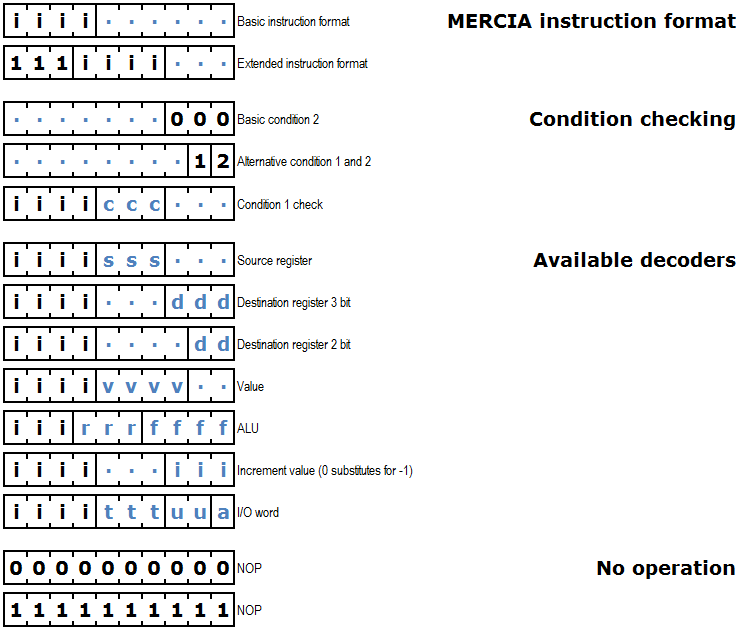
MERCIA's instruction set consists out of a basic set of 14 two operand instructions and 16 one operand extended instructions. The instruction set is entirely defined by DIP switch settings. However there are some conditions that need to be met:
1. instructions can only use the operands which there are operand decoders available for;
2. both 0000000000 and 1111111111 will result in no operation (NOP);
3. the basic or extended instruction formats that need to be met.
The figure below shows the instruction format, the condition checking and the available decoders subsequently.
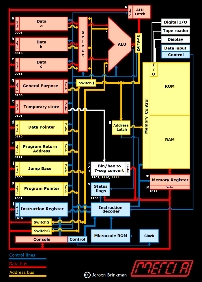
Registers
MERCIA contains 12 registers, namely the following:
|
|
Register |
Code |
Use* |
Usage |
|
a |
Data A |
0001 |
I |
ALU input & output |
|
b |
Data B |
0010 |
I |
ALU input & output |
|
c |
Data C |
0011 |
I |
ALU input & output |
|
g |
General Purpose |
0100 |
I |
General purpose register |
|
t |
Tempory Store |
0101 |
I |
Used by the Microcode to store intermadiate results and to access the binary to BCD convertor |
|
d |
Data Pointer |
0110 |
I |
Pointer to data arrays |
|
r |
Program Return |
0111 |
I |
Return address after an execute |
|
j |
Jump Base |
1000 |
M |
Used for relative addressing, in casu the first byte of a program |
|
p |
Program Pointer |
1001 |
M |
Stores the address of the next instruction to be executed. |
|
i |
Instruction |
1010 |
M |
Contains the instruction that is executed |
|
m |
Memory |
1011 |
M |
In- and output buffer for memory |
|
s |
Status flags |
1100 |
M |
Status bits used for conditional jumping |
|
1,2,3 |
Binary to 7-segment |
11 01-11 |
M |
1 (MSB), 2, 3 (LSB) |
* Can be reached by every Instruction or only the Microcode
Latches and Switches
The latches are created to increase the performance of the computer.
|
|
Latch |
Code |
Use* |
Usage |
|
A |
ALU latch |
- |
M |
Used to store ALU results |
|
B |
(Memory) address latch |
- |
M |
Enables to hold the address without occupying the address bus |
* Can be reached by every Instruction or only the Microcode
The ALU result latch makes it possible to combine several actions into one microcode step. As a result of that, the microcode will be about 10%-15% faster. It also enables the possibility to write the ALU result in one of the input registers. This also increases the speed of computer, for instance by multiplications.
The Address latch makes it possible to rewrite the content of a memory address after the (destructive) read of that address, within the memory unit.
Also the switches are solely designed to increase speed en efficiency of MERCIA. There are four switches:
- Input switch (I): connects the address bus with the memory (default) or with the ALU.
- Output switch (O): connects the ALU with the databus (default) or with the memory.
- Shortcut switch (S): connects the databus with the ALU.
- Connection switch (C): connects the databus with the addressbus.
Those switches enable the following functionality.
- Incre
: - The input is switched to the ALU.
- The program pointer (P) is connected to the address bus.
- Its value is incremented by the ALU
- The result is stored in the ALU latch.
- The program pointer (P) is cleared and connected to the databus instead
- The program pointer (P) receives the incremented value
Use absolute addressing
- Registers a, b and c can be connected to the memory by feeding the value to input a (via an OR-function, since input b is not connected), through the ALU and through the output switch to the memory. The registers d, p, r, j and t are connected to the address bus as well and therefore directly to the memory.
Use relative addressing:
- a, b or c are feed through the input selector to ALU input a, the other registers are connected to the address bus and via the input switch to ALU input x.
- The jump base is connected to ALU input y.
- Both values are added in the ALU.
- The added result is connected via the output switch to the memory.
ALU
MERCIA has a very powerful ALU that uses only 7 SPDT relay’s per bit. It has 16 functions and is able to:
- Do all the logic instructions, AND, NAND, OR, NOR, XOR, XNOR and NOT.
- Add, subtract, negate (change sign), increment and decrement.
- Shift left and right, both circular and non-circular.
- Fast multiply and divide with the use of ROM subroutines.
- Increment the program counter and calculate the memory address when relative addressing is used.
The ALU is controlled by a register controller that determines the input- and output registers and an operator controller that generates the steering signals and contains the 4-digit 7-segment display information to show the ALU-instruction that is executed.
Memory
MERCIA has three types of memory:
- Zero page relay-based I/O memory (16 bytes)
- DIP-switch based Read Only Memory (496 bytes)
- Capacitor-based Random Access Memory (512 bytes)
The computer does not determine between the types of memory. For instance the memory write instruction will allow to write to the ROM, although that is physical impossible.
Instruction decoding
The MERCIA the instruction decoding is controlled by DIP-switch ROM’s. This support the change of the MERCIA instruction set, as long as there is a decoder available for the operand. Every instruction is looked up in a 16 words by 50 bits instruction map. This instruction map contains:
- the 3-digit 7-segment display information to show the mnemonic of the instruction that is executed;
- the operand enabling, which operand decoders need to be activated;
- which conditionset need to be used: default or alternative.
- the icrocode start addresses: for each end every eight combinations of the two condition bits, the start address for the microcode.
The two condition sets are specified the following table.
|
|
Condition bit 1 |
Condition bit 2 |
|
Default |
Jump condition = status |
NOT(bit0 AND bit1 AND bit2) |
|
Alternative |
Bit 1 of instruction |
Bit 0 of instruction |
The default conditions are always calculated and result in 4 separate condition paths. For every path the start address of the first microcode instruction is specified in the instruction ROM . When a path is not relevant, the microcode start address is set equal to the value specified in the first path. Conditional jumps can be made if a value is zero, NOT zero, negative, positive, positive OR zero, even, or if an overflow occurs.
MECIA’s clock executes the microcode stored in the 96 words of 40 bits Microcode ROM. This microcode ROM contains:
- A bit that indicates when a new microcode start address must be loaded from the instruction ROM.
- The operand switching: connect the operands stored in the bits 0-5 of the instruction to the corresponding decoders.
- The several control signals that control the ALU, the registers, the switches and latches and the memory of the computer.
- The microcode address of the next microcode step.
Input and output (I/O)
MERCIA has five I/O devices and an operator console. The five I/O devices are:
- A 10 digit 7-segment display.
- A 4 digit multifunctional hexadecimal keyboard.

- An optical paper tape reader.
- A 10 bit digital input and 10 bit digital output interface.
- A 10-bit binary to 3 digit 7-segment decoder.
May 2016, Jeroen Brinkman