The purpose of an instruction decoder is to decode or translate the instruction in a number of signals that will implement the execution of this instruction on its operands. An execution of an instruction always needs to be done in several steps. And during each step certain signal lines have to be activated. Several methods are known to generate these signals. Combinatorial logic can be used, or a signal generator in combination with a diode matrix.
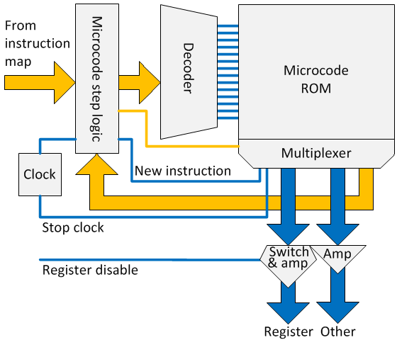
MERCIA uses another and unique approach, based on a an instruction map and microcode ROM. The so called instruction map generates all the properties of an instruction. One of those is the start address for the microcode. For different conditions, different start addresses are kept in this instruction map. The microcode ROM generates the necessary signals: the signal lines are represented by the columns and the microcode steps by the rows. Each instruction is executed by the signals contained in several microcode steps and thus rows. Each microcode step also contains the address of the next microcode step as well as a bit that indicates a new instruction and therewith start address must be loaded.
The MERCIA instruction decoder will be explained in the following nine paragraphs, namely the:
1. instruction decoder overview;
2. instruction map: generating all the properties of an instruction;
3. NOP handling: logic to deal with No OPeration instructions;
4. conditional jump logic: making it possible to make a conditional jump;
5. operand enabling: enabling the operands of an instruction;
6. microcode ROM: generating the control signals that execute the instruction;
7. defined paths through the machine;
8. clock and microcode step logic;
9. console: (remote) control of the clock and therewith instruction execution.
They will be discussed subsequently in separate paragraphs.
Overview
A functional block diagram of all the components of the instruction decoder. The Basic and Extended coder/decoder together form the instruction map.
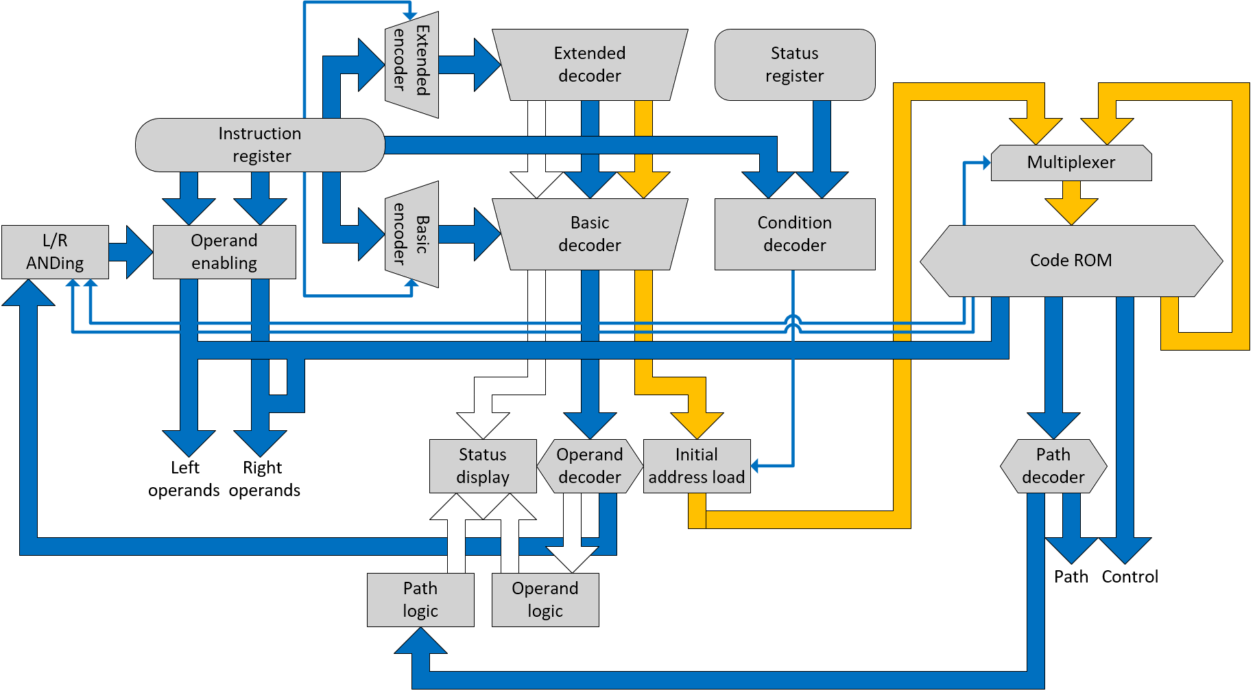
The instruction map
The most effective instruction set is a set where every combination of bits is a meaningful instruction. This causes a problem for instructions who has none operands of only one operand. For MERCIA this is solved by the extended instruction set as can be found in the article about the Instruction set.
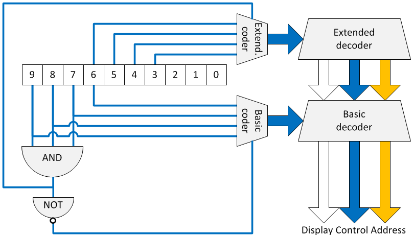
For the basic instruction set bit 6- 9 are used. Basic instructions always have two operands. For the extended set bit 3-6, while bit 7-9 are always 1. This extended instruction set has none or only one operand.
An AND-gate is used to decide if the instruction is an basic or extended instruction. Both decoders – the basic as well the extended decoder – are always active. But only one decoder will be enabled by this AND-gate.
The instruction map stores the following instruction properties:
• 21 lines for the three seven segment displays, who contain the 3-letter mnemonic of the instruction;
• 3 bit, expanding to 8 lines for selecting the proper operands for the instruction;
• 7 lines to select the Microcode ROM start address.
• 3*3 lines (bit 2- bit 0) to select the Microcode ROM jump address.
NOP handling
A very special instruction is the NOP or No Operation. This instruction is created to deal with memory problems. If a memory bit got defect, for instance a single DIP switch can’t be switched off, it is practical to be able to neutralize the byte. Therefore an instruction with solely 1 or solely 0 will act as a NOP instruction. Some logic has to be created to be able to use the instruction 0000xxxxxx and 1111111xxx also for other purposes.
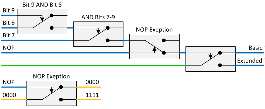
The instruction register has NOP detection, as described in the register article. IF NOP is detected, two relays are switched on to select instruction 1111xxxxxx in the basic instruction map. The first relay ensures that the basic set is always chosen (top circuit diagram). The second relay is placed behind the basic map decoder for instruction 0000 and forces this to basic instruction 1111 (bottom circuit diagram).
Conditional jump logic
Conditions are used for conditional jumping as well as for instruction variants. An instruction variant is an instruction that has a two bit function code that determine which of four variants need to be executed. There are two sets of conditions: basic conditions and alternative conditions. The two condition sets are specified the following table.
|
Condition bit 1 |
Condition bit 2 |
|
|
Basic |
Jump condition = status |
NOT(bit0 AND bit1 AND bit2) |
|
Alternative |
Bit 1 of instruction |
Bit 0 of instruction |
For the alternative conditions up to four different execution paths for each individual instruction.The instruction map determines if the basic or alternative set must be used.
The condition decoder determines the values of both conditions and is shown in the next circuit diagram. The jump condition (bit 3– bit 5) is feed through a decoder resulting in only one line being 1. The corresponding AND-port will feed the status bit from the status register to the condition 1 output. Condition 2 is set to 1 when bit 0 – bit 2 are all 0. The alternative condition set connects bit 1 to condition 1 and bit 0 to condition 2
The condition decoder is shown in the next circuit diagram.
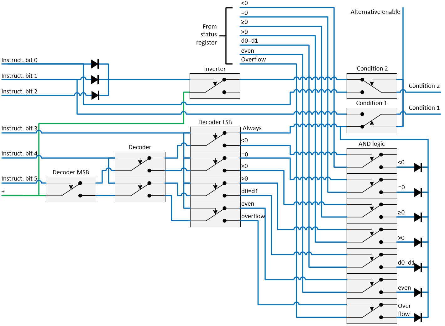
The initial start address for the microcode ROM is determined in the following way.
1. By default the 7 bit Microcode start address is used (sssssss).
2. Depending on the values of condition 1 and condition 2 an alternative (conditional) start address is selected (ssss111, ssss222 or sss333)
The following relay circuit is used to implement this solution.
Operand enabling
Every computer instruction consists out of:
1. an operator or function and
2. optional one or more operands.
The operator tells the computer what to do and the operand is the entity on which this operation is performed. For instance: COPY register a TO register b. Here COPY is the operator and register a & b are the two operands.
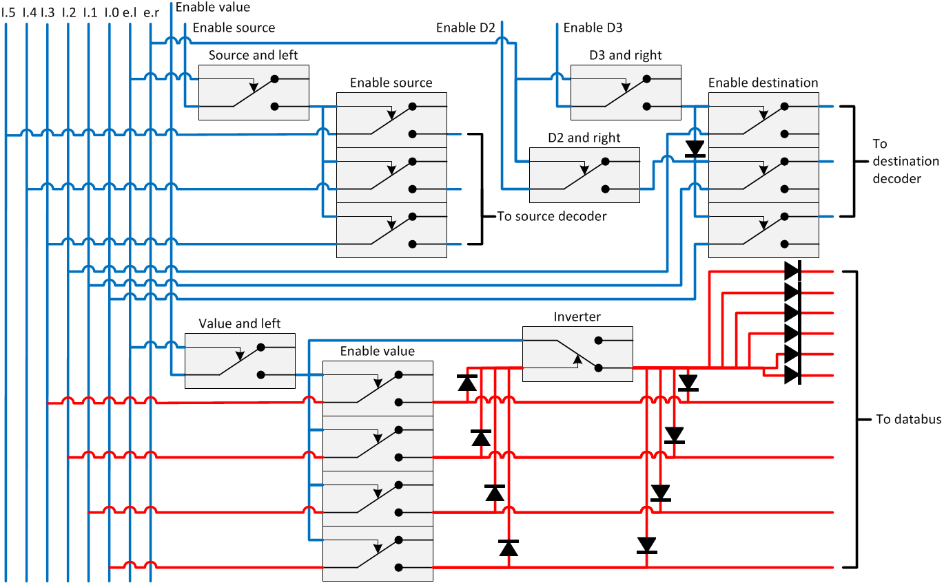
During execution, operands are enabled in two steps. First, the instruction map defines the operands that the instruction uses. Secondly, the microcode determines when the operands must be used. This is done, so that the microcode can have exclusive access to the operand decoders, without being interfered by the instruction operands. Five operand groups are in use:
• source register control (l);
• destination register control (r), both the 2-bit destination as well as the 3-bit destination (r) operand;
• instruction embedded literals, both the value (l) as well as the increment (r);
• I/O functions (l)
• ALU functions, both the register usage (l) and the ALU function to use (r)
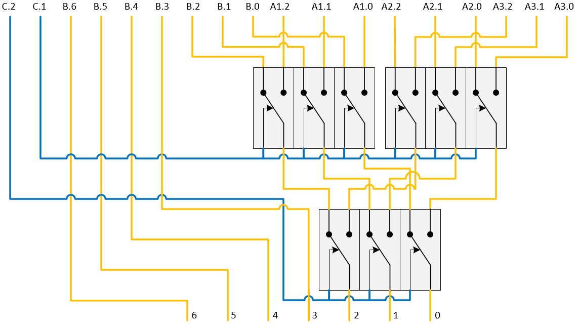
MERCIA has instructions with a maximum of two operands, so the operands are activated by two microcode signal lines (left and right). Left (l) will activate the first operand, right (r) will activate the second operand. Three representative operand enablers are sketched in the next circuit diagram:
1. the source register enabler is also representative for the I/O- and ALU-functions.
2. the destination register enabler shows how both the 2-bit and 3-bit destination code is enabled;
3. the value enabler shows how is dealt with the conversion from value 0 to value -1.
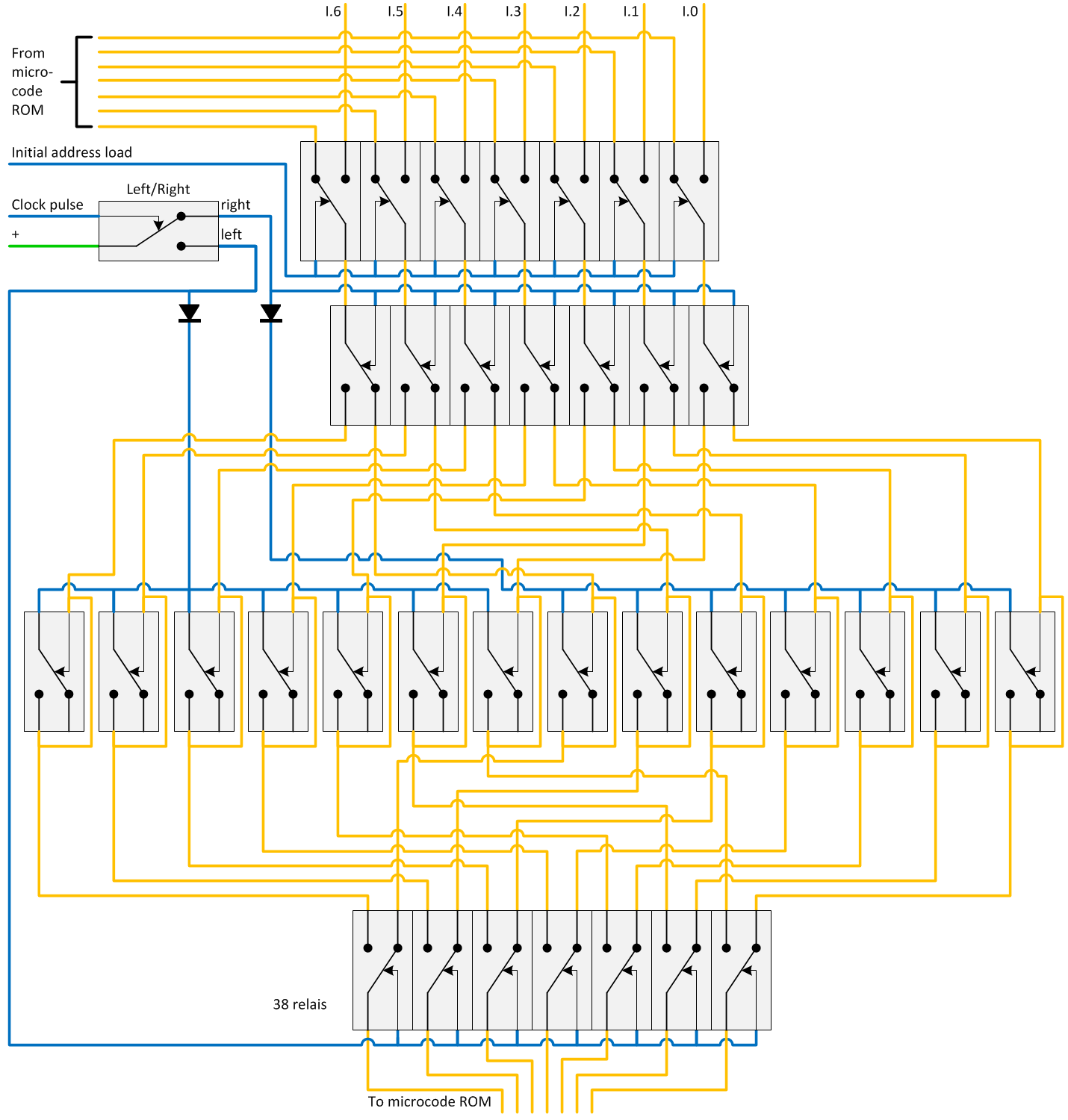
The microcode ROM
For the instruction decoding or translating an instruction in several microcode steps, a finite state machine (FSM) is used. The use of a FSM makes it possible to have a variable number of microcode steps for each instruction. And that significantly enhances the computer speed. For MERCIA this FSM is implemented by using a 96*40 bit DIP-switch Microcode ROM. The block diagram of this Microcode ROM is given below. The microcode ROM is organized in a 48*80 configuration, so a multiplexer is needed to select the left or right 40 bits. Fetching a new instruction, e.g. loading a new start address from the instruction map, as well as stopping the clock are also controlled by the microcode.
The 40 microcode bits aren’t nearly enough to control the computer. Several decoders are used to generate the 198 necessary signals. This is shown in the next table.
|
|
Signal group |
Bits |
Decoder |
Signals |
|
1. |
Fetch new instruction |
1 |
- |
1 |
|
2. |
Activate instruction operands |
2 |
- |
4 |
|
3. |
ALU control |
5 |
15 relays |
21 |
|
4. |
Latch clearing |
3 |
- |
3 |
|
5. |
Path select |
4 |
15 relays |
6 |
|
6. |
Source register |
7 |
46 relays |
31 |
|
7. |
Destination register |
7 |
54 relays |
39 |
|
8. |
Memory control |
3 |
- |
3 |
|
9. |
Clock off |
1 |
- |
1 |
|
10. |
New MC ROM address |
7 |
87 relays |
96 |
|
|
Total |
40 |
209 relays |
208 |
These signal groups are described below.
Fetch new instruction
When all the steps of an instruction are done, a new instruction need to be executed. This bit tells MERCIA to load a new start address for the microcode ROM.
Activate instruction operands
The instruction operands use the same decoders as the microcode does. Therefore the microcode must have an option to enable and disable these instruction operands. When disabled, the microcode has complete control over the computer. This is necessary, for instance to increment the program pointer in order to point to the next instruction.
Since MERCIA has a maximum of two operands, there are two bits reserved for this purpose.
ALU control
The ALU is used for several purposes. Foremost it is used to do calculations. But it is also used as incrementer of the program pointer and calculator of the absolute memory address when relative memory addressing is used. The ALU is controlled by 10 signals, from which 4 signals contain the operator or ALU function.
Path select
Data and addresses can be routed through MERCIA in different ways. Those ways are called paths and are coded by a four bit code.
Source and destination register
All registers, including the status register and the 7-segment converter, are controlled by the register control and both decoders. In order to facilitate the use of managing registers with the console, the amplifiers for the register control are combined with a switch. There is a button on the console to switch them off, so they don't interfere with the console.
Memory control
Memory control reads, writes and clears the ROM, RAM and I/O Relay memory.
Clock off
Stops the clock and halts MERCIA
New microcode address
The microcode is implemented as a Finite State Machine. So every microcode step includes the microcode address for the next microcode step. This facilitates microcode to be used by more than one instruction.
The paths
MERCIA has several connection possibilities to connect the components to each other. The path decoder is used to lay predefined paths through the machine.
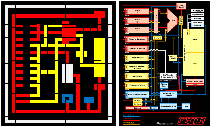
In order to make those paths visible a path status panel is incorporated. This panel contains a schematic diagram of MERCIA.
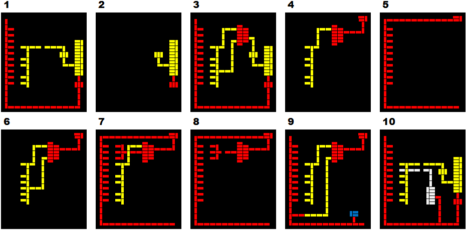
There are ten paths defined. Those paths are used for the following purposes.
| 1. | Is used to store or retrieve an memory value, using absolute addressing. |
| 2. | Is used to restore a value after it has been read. |
| 3. | Is used to store or retrieve an memory value, using relative addressing: the value of the jump base is added to the memory address. |
| 4. | Is used to increment the program counter, and write the result to the l latch. |
| 5. | Is used to write the result in the l latch in to a register. |
| 6. | Is used to calculate the next relative address for a jump. Because the p register is both input and output, the latching function of the ALU is used. |
| 7. | Is used to increment or decrement any register. |
| 8. | Is used for the regular (program controlled) ALU functions |
| 9. | Is used to increment using a literal (value within the instruction). |
| 10. | Is used to display a digit on the 7-segment display, that is part of the memory. |
The clock and microcode step logic
The clock of MERCIA is build out of three parts:
1. the logic to control the starting and stopping of the clock.
2. the oscillator that generates an asymmetric square wave;
3. the T flip-flop that converts it in a symmetric square wave;
The control lines originate in the console. The Step, Next and Stop signals are coded, because the console uses a 50pin connector and are not enough lines available to give every signal its own line/pin. Run will start the clock and Stop will stop the clock. Step will execute one microcode step, Next will execute the next instruction and Halt will stop the clock only when the instruction is finished. Fetch instruction is the microcode signal that fetches a new instruction start address from the instruction map. The relay logic for the clock is shown in the next circuit diagram.
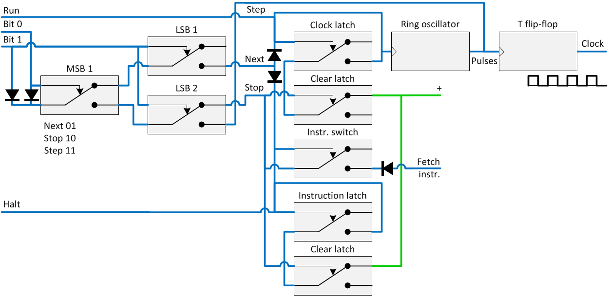
Left and right, the output of the clock, is input for the microcode step logic. For this two alternating registers are used, referred to as left and right. When the left register is used to point to the current microcode address, the right register is loaded with the new address from the instruction map and vice versa. MERCIA’s clock generates the signals to alternately change between the left and right register. The one bit principle is shown below.
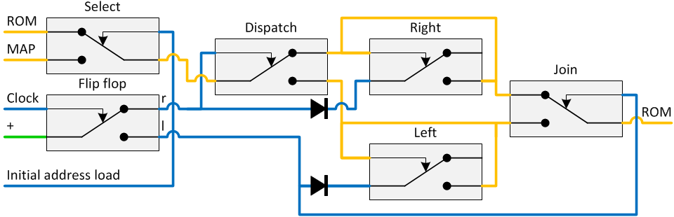
The circuit diagram for the complete state machine is shown here.
The console
Every computer needs a operator console. Since all the important computer information is shown on the panels, MERCIA’s console has mainly input switches. The only exception on that is the 7-segment display that shows the current active register. The console is connected with a 37-core cable to the register panel.
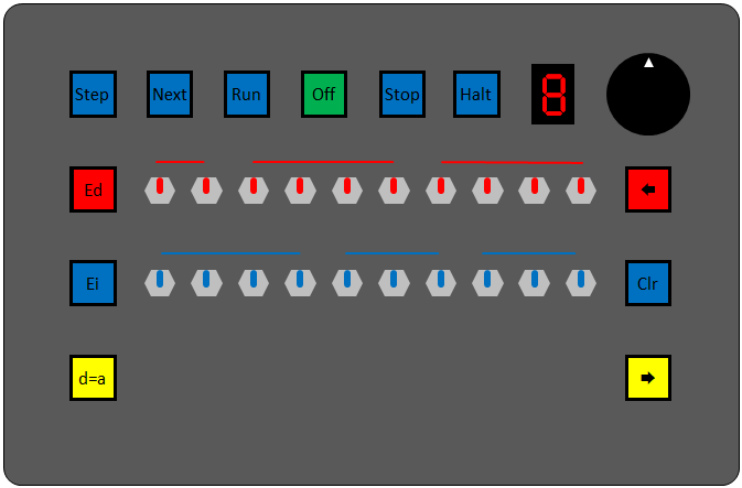
The functions of the buttons are the following:
|
Off |
Emergency power cutoff of MERCIA in case a short circuit occurs. |
|
Run |
Start MERCIA’s clock |
|
Stop |
Immediate stop MERCIA’s clock |
|
Step |
Execute a single microcode step |
|
<Next |
Execute the next instruction |
|
Halt |
Stop after this instruction |
|
Ed |
Enable data: make the data switches active and disable the microcode register ontrol |
|
d=a |
Connect the data bus directly to the address bus, so the memory address can be loaded by use of the red data switches |
|
Ei |
Enable instruction: disconnect the instruction register and connect the 10 blue instruction switches |
|
|
Select one of fifteen registers and connect this with the source decoder. |
|
Å |
Connect that register to the data bus |
|
Clr |
Clear that register |
|
Æ |
Connect that register to the address bus |
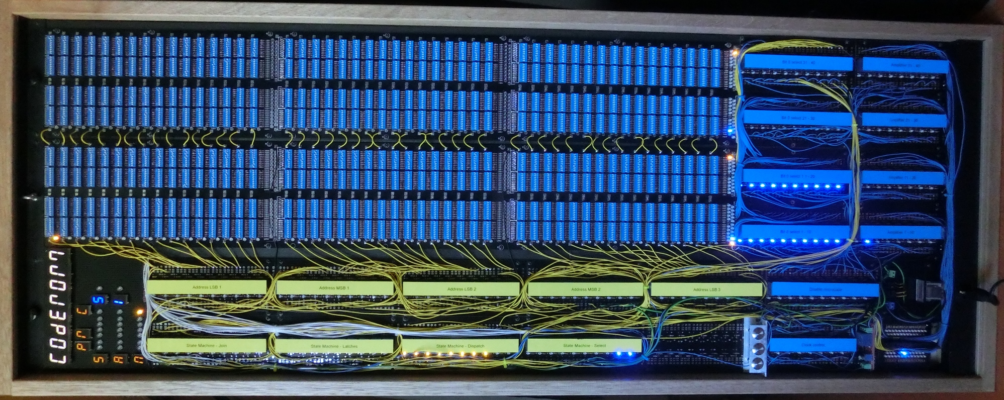
April 2017, Jeroen Brinkman